Survey and Data
Initial Airborne TDEM-Magnetic Survey
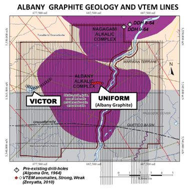
Fig. 282 VTEM survey lines and EM anomalies for the initial airborne EM survey flown in 2010.
The Albany Project airborne EM-magnetic survey for Zenyatta consisted of >10,000 km of helicopter time-domain EM (TDEM) and magnetics over multiple (28) blocks from March 17 to May 19, 2010 ([Leg10]). The survey was performed using a higher power VTEM (versatile time-domain electromagnetic; [WIM04]) prototype that featured a larger loop diameter (35 m) and higher dipole-moment (0.84 M nIA) that would later develop into VTEM \(\!^{MAX}\) ([Kil11]). The survey was flown along 150 m spaced, north-south oriented lines and east-west tie-lines at 700-1500 m spacings. The Albany graphite survey claim block (4F) consisted of 1181 km covering a 206 m \(\! ^2\) area (Fig. 282), flown at an average EM sensor height of 53 m and an avg. magnetic sensor clearance of 75 m.
Supplementary Ground TDEM Survey
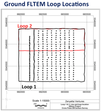
Fig. 283 Ground TDEM loop locations and data sampling at the Albany graphite project.
The Albany Project ground EM survey consisted of 12 line kilometers surveyed from 2 loop configurations with the Crone Time Domain Pulse EM system using a 50 ms time base and a Crone surface induction coil measuring the in-line and vertical components. As the target was described as possible pipe-like structures from previous airborne TDEM results, it was anticipated that surface TDEM surveys could be influenced by both the top, presumably the flat edge of the pipe, as well as the vertical faces if the pipe had a significant depth extent. As shown in Fig. 283, the survey design incorporated an in-loop mode (Loop 1; Fig. 283) to couple with the top, flat, (or relatively shallow dipping), edge of the body and an offset loop mode (Loop 2) to couple with the steeply dipping edges. Loop 1 was surveyed in an in-loop mode with a 1200 m by 1500 m loop, with a peak current of 11 Amps, covering 11 lines ranging from 1000 m to 1100 m in length. Line spacing within the loop was 100 m, with station spacing ranging from 25 m to 50 m. The same lines were resurveyed with an offset loop (Loop 2) at 12 Amps. Loop 2 utilized the Northern 500 m x 1500 m section of Loop 1.