Purpose
Here, we describe a host of instruments used for UXO surveys along with some of their pros and cons. Properties of the transmitter and receiver are discussed.
Survey
Instruments designed for UXO applications come in a wide variety of geometries ranging from single loop, man-portable systems to cart systems with multiple transmitters and receivers. Each system has its advantages and disadvantages. As a result, it is important to choose a UXO system which works well for a particular setting. Frequency domain systems have been used for decades, however, modern time domain systems are currently a more popular choice. Aspects of UXO surveys as they relate to instrumentation are discussed here. Aspects of survey design are discussed here.

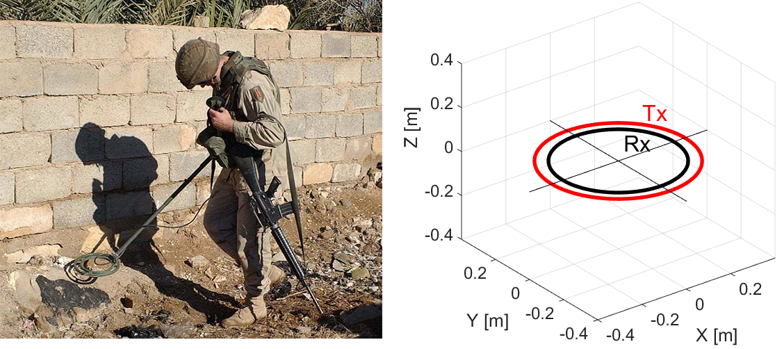
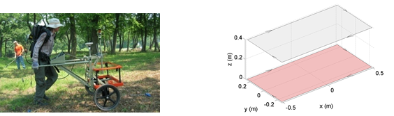
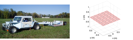
Fig. 262 Man-portable vector (MPV) system (left). TEMTADS system (right).
The Source and Receiver
Transmitter
For UXO systems, inductive loop sources are used as transmitters. Each transmitter loop is comprised of a coil of wire which carries a time-varying electrical current; which produces a time-varying primary magnetic field.
Transmitter loops can be square or circular in shape. For single-loop systems, the transmitter loop is generally oriented horizontally. For multi-loop systems, transmitter loops can be orthogonal to one another and/or organized as part of an array. Multi-loop configurations allow the transmitter to illuminate targets from multiple directions at a single location. Mobile systems (EM-61, MPV, TEMTADS, etc…) use transmitter loops with dimensions anywhere from 10s of centimeters to roughly a meter. Large loop systems use a stationary transmitter loop with dimensions up to 10s of meters (UltraTEM).
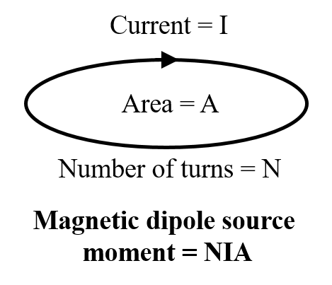
Fig. 263 Representation of the dipole moment for an inductive loop source.
The strength of the transmitter’s primary field is dependent on its dipole moment. For a given transmitter loop, the dipole moment is given by:
where \(I\) is the current within the loop, \(A\) is the loop’s cross-sectional area and \(N\) is the number of turns for the coil. As we can see, the strength of the transmitter’s primary field can be increased by increasing the current amplitude, the cross-sectional area or the number of turns. Increasing the transmitter’s dipole moment allows us to improve the signal to noise ratio of UXO systems.
Receiver
For UXO systems, coils of wire (receiver loops) are used to measure the secondary fields generated by buried conductors. The change in magnetic flux through each receiver loop, due to the target’s response, induces an electromotive force (EMF) within the loop. Ultimately, the receiver measures the voltage which results from the induced EMF. For both frequency domain and time domain systems, the induced EMF within a receiver loop is illustrated below.
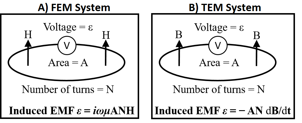
Fig. 264 EMF induced within a receiver loop. A) FEM receiver loop. B) TEM receiver loop.
Frequency domain systems measured real and quadrature components of the secondary field. Time domain systems generally measure the target’s \(dB/dt\) response; although there are systems capable of measuring \(B(t)\) directly. Receiver loops are only sensitive to components of the secondary field parallel to their normal vector. Thus in order to obtain 3-component data, multiple orthogonal receiver loops must be used.
As we can see from the illustration above, the EMF induced within the receiver loop is proportional to both the loop’s cross-sectional area (\(A\)) and the number of turns (\(N\)). Because the EM anomalies from UXOs are so compact, receiver coils with smaller cross-sectional areas must be used in order to accurately quantify the target’s response at a particular location. The corresponding decrease in signal to noise ratio from small receiver loops is overcome by using coils of wire with many turns.
Transmitter Source Signal

Fig. 265 High frequency (left) and low frequency (right) signals contained within transmitter waveform.
Frequency Domain
FEM systems transmit harmonic signals at one or more frequencies. Lower frequency signals penetrate deeper into the Earth whereas higher frequency signals offer better resolution at shallow depths. Typically FEM systems operate using frequencies between 1 kHz and 20 kHz.
Time Domain
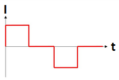
Fig. 266 Bi-modal boxcar waveform with 50% duty cycle.
When operating in the time domain, we are generally interested in the UXO’s transient response; that is, the response to step-off excitation. Most TEM systems use a bi-model boxcar current waveform with a specified duty cycle. The data are collected during the off-time. So long as the time-width of the boxcar is sufficiently long, it may be used to accurately approximate the transient response over the set of measured time channels. For most systems, the time-length of the boxcar waveform is on the order of 10s of milliseconds.
Survey Configurations
Below are a set of electromagnetic sensors which have been applied to UXO detection and classification problems. This is not a comprehensive list of electromagnetic sensors, but is intended to illustrate the recent evolution towards configurations with multiple transmitters and receivers. Although FEM systems have been used for decades with varying levels of success, modern TEM systems are more commonly used for UXO detection. As a result, most of the instruments presented here will belong to the class of TEM systems.
Frequency-Domain Systems
Coincident Loop Systems
Coincident loop systems are by far the most common configuration for FEM UXO surveys. These systems generally consist of a circular transmitter loop and a circular receiver loop which lie on the same plane. This allows for easy removal of the transmitter’s primary field from the data, thus isolating the target’s response. The diameter of the transmitter and receiver loops are generally on the order of 10s of centimeters. Although this type of system is very portable, the data collected cannot be as easily used to locate and classify targets. As a result, these types of systems are becoming less common. A variation of this particular instrument is the Terraplus GEM-3 system which operates within a bandwidth of 30 Hz to 24 kHz. This system can be equiped with 40 cm, 64 cm or 94 cm diameter heads.
Time-Domain Systems
EM-61
The Geonix EM-61 is a time-domain instrument with a single horizontal transmitter loop and a single receiver loop; thus it only measures a single vector component of the TEM response. Several versions of this instrument are available which use different loop sizes (MK2 A, MK2 HH and MK2 marine). Smaller transmitter and receiver loops are generally used to find smaller objects at shallower depths. The MK2 marine version can be used in underwater applications.
TEMTADS
The TEMTADS system is comprised of 25 coincident transmitter-receiver pairs. Each transmitter and receiver loop is square, with a side length of 40 cm. The sensor array measures the vertical TEM response due to illumination of the target from multiple orientations. By mounting this system onto a cart, it may be used to survey large areas in a relatively short amount of time. The addition of multiple transmitters and receivers allows for better characterization of compact TEM anomalies. The popularity of this survey configuration has decreased recently with the development of the Metal-Mapper 2x2 system; which requires the collection of less data while using transmitter loops oriented in three orthogonal directions.
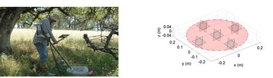
MPV
The man-portable vector (MPV) instrument is comprised of a 50 cm diameter transmitter loop and an array of 5 receivers. Each receiver measures 3-component data, resulting in 15 transmitter-receiver pairs. This instrument was designed to improve maneuverability in rugged terrain. The use of small receiver loops allows for accurate characterization of compact TEM anomalies.
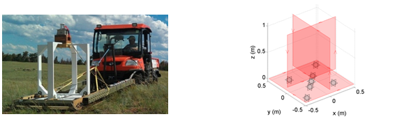
Metal-Mapper
The Geometrics Metal-Mapper is a time-domain instrument with 3 orthogonal transmitter loops (1m \(\times\) 1m) and a horizontal array with 7 receivers. Each receiver measures 3-component data, resulting in 63 transmitter-receiver pairs. Because the Metal Mapper illuminates targets from multiple orientations, it has an advantage over single transmitting loop systems. The use of small receiver loops allows for accurate characterization of compact TEM anomalies.
Metal-Mapper 2x2
The Metal-Mapper 2x2, sometimes referred to as the TEMTADS 2x2, combines the advantages of the original TEMTADS system with those of the Metal-Mapper system. The Metal-Mapper 2x2 is has a 2x2 array of orthogonal transmitter loops; which makes 12 transmitter loops in total. This system is relatively new but has begun to replace the orignal TEMTADS and Metal-Mapper systems for most applications.