Purpose
Here, we briefly discuss the compromise between probing distance and resolution. In addition, we consider several external source of noise which can contaminate GPR data and a manner in which it may be reduced.
Practical Considerations
Probing Distance versus Resolution
On the right we see several radargrams corresponding to data collected over two buried tunnels (hyperbolic features). Each radargram was collected using a different frequency.
By using a 200 MHz central frequency, we are hoping to obtain a high resolution radargram. However, the attenuation of radiowaves is more severe at higher frequencies. As a result, the GPR signal does not penetrate deep enough to image either of the tunnels. At 100 MHz, both tunnels become partially visible in the radargram (hyperbolic signatures). This is made possible because because the probing distance is larger. In the 50MHz radargram, both tunnels are easily recognizable. This is made possible because the probing distance is now large enough. Notice however, that the hyperbolic features in the radargram are slightly less distinct.
We can see from this example that there is a compromise between resolution and probing distance. It is important to choose a frequency which is high enough to image sufficient small features. However, the probing distance of the background medium must be large enough to obtain a return signal.
Shielding External Sources of Noise
Below are some sources of noise relevant to GPR and their impact.
Radiowaves from Other Sources

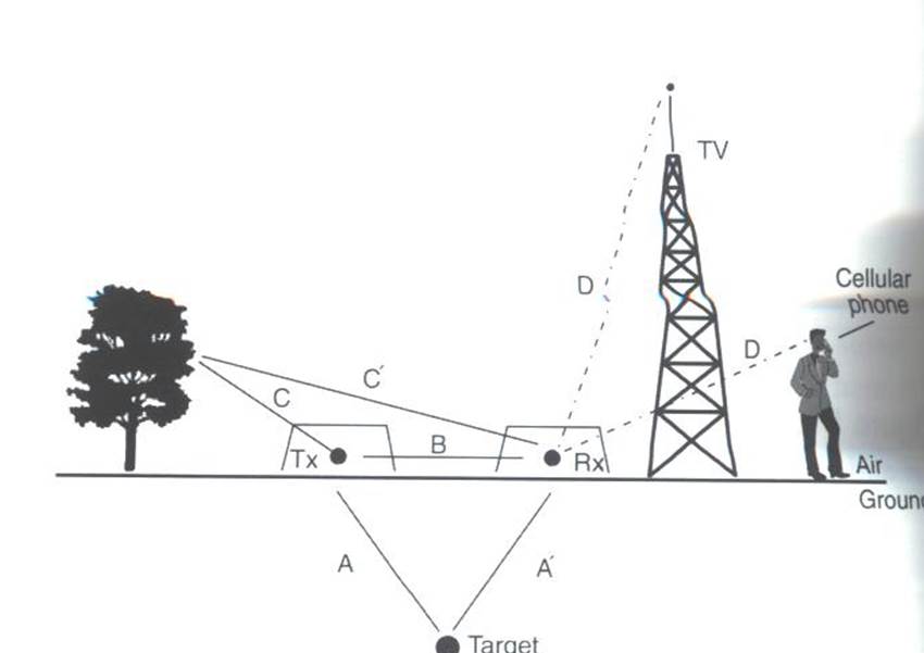
Fig. 251 Some external sources of noise related to GPR system, which can be reduced through shielding.
Much of 21st century communication is made possible with radiowaves. Cellular phones, radio towers and other transmitting systems all use radiowave frequencies to transmit information through the air. These signals can be measured by the receiver and have the potential to mask responses from desired targets. To limit the effects of external sources, the transmitter and receiver are frequently protected by a shield (as depicted in the image).
Returning Signals from Above-Ground Objects
GPR is used to gain information about structures below the Earth. However, since radiowaves propagate through the air, it is possible to measure returning signals from nearby objects as well. This is common in urban and wooded environments where GPR signals can reflect off of buildings and trees.

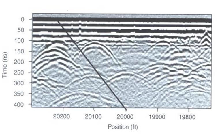
Fig. 252 Zero-offset radargram example containing returning signals from nearby trees.
On the right, we see an example of a radargram for a zero-offset configuration. The survey was performed in a wooded area without using a shield. Because the trees acts as point reflectors, they produce hyperbolic signatures in the radargram. Using the slope on either end of the hyperbola, we find that the propagation velocity associated with this reflection is \(2/c\); this is demonstrated with a line. This verifies that the signature must correspond to an object which is above the ground. And we can infer that signatures after 100 ns correspond to nearby trees.
To avoid measuring signals such as these, shields may also be used on the transmitter and receiver. However, if signals from above ground objects are present in the radargram, they can be be identified for zero-offset configurations by their slope.