Survey
Purpose
To provide an overview of the basic airborne TDEM system configuration and commonly used instrumentation.
System Configuration
Transmitter
Loop: Because an ATEM system covers a wide bandwidth using rapid change in the transmitter current waveform, only one transmitter loop is needed in a system.
Platform: If using a helicopter, the transmitter loop is usually attached to a round frame towed after the helicopter through a cable. If using a fixed- wing airplane, the transmitter loop is shaped as a diamond attached to the nose, tail and wingtips of the plane.
Peak current. The actual peak current that goes through the coil may vary depending on the power of the generator and other constraints. A transmitter loop mounted on a fixed-wing aircraft usually carries larger peak current thanks to the lifting capability of a fixed-wing for more powerful generators.
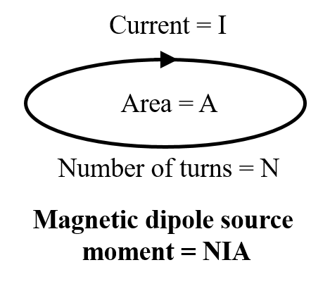
Fig. 191 Moment of an airborne EM loop source.
Moment: The strength of a magnetic dipole source is specified by dipole moment, a quantity defined as the product of the effective area and the peak current (Fig. 191). A high moment can generate greater excitations and thus improves the quality of data in a noisy environment, but the actual area and current of the loop are limited by the power supply and other practical restrictions. Modern ATEM systems are equipped with a dipole moment over 1 million Am:math:^2 to achieve a depth of penetration down to a couple of kilometers.
Waveform: An ATEM source induces a time-dependent EM fields underground by making rapid change in the transmitter current. An ATEM waveform usually consists of on-time (current is turned on and changing) and off-time (current is turned off and not changing). ATEM waveforms are usually bipolar, so some systematic errors can be stacked out. The shape of an ATEM system’s waveform is fixed, but how often a on-time pulse appears can be tuned by a parameter called base frequency (typically from 20 to 90 Hz). A lower base frequency allows a larger transmitter moment, measuring at later delay times, and thus detection of deep geology.
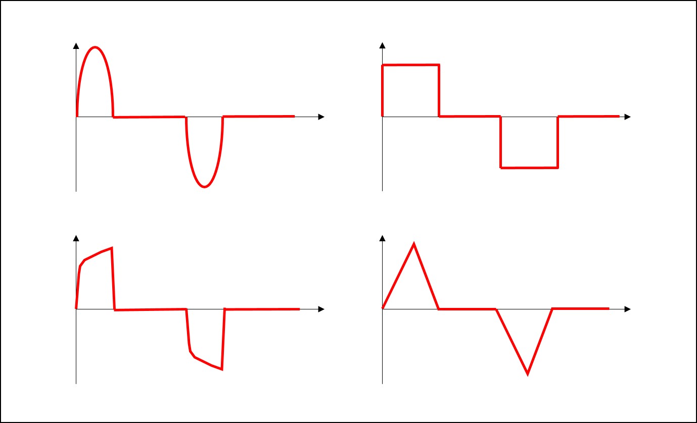
Fig. 192 Common ATEM waveforms.
Receiver
Loop: ATEM uses another loop to measure the time-derivative of the magnetic field (dB/dt), in a way similar to AFEM. At the receiver coil, an electromotive force (measured in Volt) can be induced by the primary field from the source and the secondary field from the earth. When the transmitter current is turned off during the off-time, only the secondary field is measured. The coils can be multi-turned to increase the effective area for better SNR.
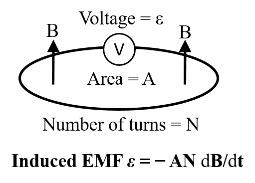
Fig. 193 The EMF measured at the receiver loop is proportional to dB/dt data.
Measurement: The induced EMF is proportional to the rate of change of the magnetic flux through the area enclosed by the loop (\(\varepsilon = - \frac{d \Phi}{d \mathbf{t}}\)). Because the loop is much smaller than the wavelength of the magnetic field in an airborne TDEM survey, the magnetic field at the receiver can be considered uniform. The total magnetic flux is then approximated by the product of magnetic flux intensity and the effective area of the receiver loop. Then the measured EMF can be used to calculate the dB/dt at the receiver (\(\varepsilon = - \frac{d \Phi}{d \mathbf{t}} = - \frac{d A N \mathbf{B}}{d \mathbf{t}} = - A N \frac{d \mathbf{B}}{d \mathbf{t}}\)), as the effective area is known. Conventionally, a time-domain system only measures dB/dt during off-time when the primary is zero, but in practice both on-time and off-time data are acquired as time series. In some cases, the on-time data can be particularly diagnostic.
Configuration
Orientation: The transmitter loop in an ATEM system is usually a horizontal loop, which is relatively easier to manufacture and implement in the field operation. The receiver loop can be much smaller, and three loops can be oriented orthogonally to measure three-component dB/dt.
Separation: Basic physical model for ATEM is a configuration called “coincident loop” or “central loop”, in which the recevier is at the center of the transmitter loop. This has been strictly used in same ATEM systems, but there are variants. For example, the receiver can be mounted to the tail of the transmitter loop or suspended above the transmitter loop. In a fixed- wing system, the receiver is usually towed a couple of hundreds meters after and below the transmitter loop. Such separation is negligible for low induction number, but must be taken into account when interpreting early time channels or over conductive region.
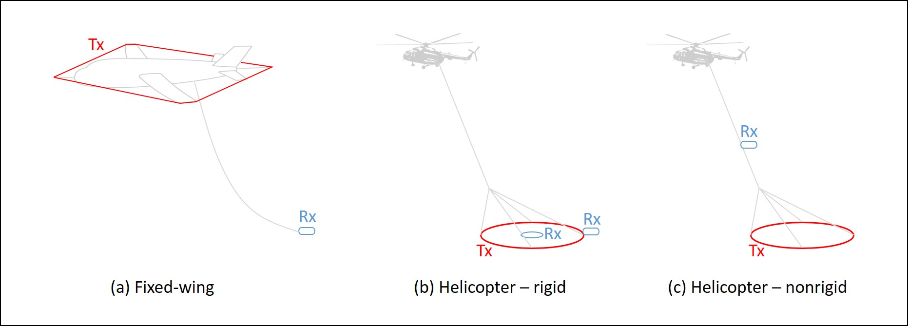
Fig. 194 Common ATEM configurations.
Field Operation
During production, a frame or bird is towed by a helicopter flying along lines and the EM data are measured during the flight.
Flight
Clearance: A helicopter-towed bird is typically at least 20 or 30 metres above the surface. A fixed-waing system flies about 100 m above the surface. Although a higher spatial resolution is desirable by flying the system as close to the ground as possible, a sufficient clearance must be maintained for safety and piloting reasons. In mountainous regions or over tall trees, the system may need to fly higher.
Line spacing: An airborne TDEM survey usually consists of a group of flight lines that are straight and parallel to each other. The spacing between lines is determined by the resolution requirement of the survey and also the geology. Typically an ATDEM system has a line spacing from 50 to 500 meters for applications from geotechnical to resource reconnaissance.
Speed: A slow-flying TDEM system can measure more sounding samples per line-kilometre. However, a higher spatial resolution comes at the cost of spending more time in air. As a trade-off, a helicopter TDEM system typically flies at a speed of about 30 m/s and a fixed-wing system at about 100 m/s.
Positioning
GPS: Differential Global Positioning System (D-GPS) units are used to collect the location of the helicopter and the bird during the flight. Location data is also collected with a base station so post-survey correction to, for example, clock error and satellite orbit are possible.
Altimeter: There are two types of altimeter that determine the actual flight height. A radar altimeter sends radio waves that reflect from the ground back to the helicopter, and times the travel time to calculate the distance. This type of altimeter is usually located in the helicopter, because it has a longer range. A laser altimeter uses a laser beam instead of radio waves. It is more sensitive in the low range than the radar, so it is often located in the bird. The altitude is measured several times in a second during a flight.
Orientation: The inertia measurement unit (IMU) is used to record the orientation of the bird. It records g-force and angular rate of the bird using accelerometers and gyroscopes.
Post-processing and corrections
The processing and correction implemented by the service providers before data delivery may include:
Base level correction
Lag correction
Moving window median and Hanning filter
Laser altitude correction for dropouts and variation
Magnetic data lag and diurnal correction and IGRF removed
Systems
This section presents commercial airborne TEM systems.
Call for contributors
If you are a service provider, or have experience with a specific AFEM system and would like to contribute, please contact us.