Reflection and Snell’s Law
Purpose
Here, we derive the propagation angles of reflected and refracted waves at a horizontal interface. Snell’s law is then used to characterize the refraction angle in terms of the complex wavenumber for both media.
Setup
Here, we will consider the reflection and refraction of a uniform, linearly polarized, homogeneous plane wave at a horizontal interface (Fig. 58). The incident wave is confined to the xz-plane. The interface is denoted by \(S\), has a normal vector \(\mathbf{\hat n}\) and separates two homogeneous media with physical properties \(\sigma_1\), \(\mu _1\), \(\epsilon_1\) and \(\sigma_2\), \(\mu _2\), \(\epsilon_2\).
For the setup in Fig. 58, the incident wave (\(k_i\)) arrives at angle \(\theta_i\). Once this wave reaches the interface, it breaks into two parts, a reflected wave (\(k_r\)) and a transmitted wave (\(k_t\)). The transmitted was experiences a change in propagation direction, thus it is a refracted wave. The reflected and refracted waves travel in directions characterized by angles \(\theta_r\) and \(\theta_t\), respectively.
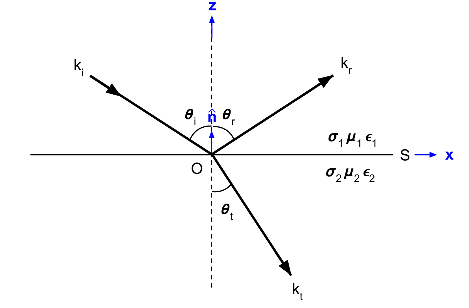
Fig. 58 Geometry for Snell’s law. Modified from [WH88] Figure 3.1.
Snell’s Law, Reflection and Refraction
The reflection and refraction angles (\(\theta_r\) and \(\theta_t\)) can be derived by considering either the electric field or the magnetic field carried by the incident EM wave. Here, we will derive these angle by considering an electric field. The respective incident, reflected and refracted waves are given by:
where \(\mathbf{k}\) is the wave vector (Poynting vector) for each wave and:
Within formative laws, we discussed the interface conditions required for electric and magnetic fields. They state that components of the electric field parallel to surface \(S\) must be equal across the interface. As a result:
Using the previous three expressions, we find that:
and
According to Eq. (136), the reflected angle and the incident angle relative to \(\mathbf{\hat n}\) are the same. Eq. (137) is known as Snell’s Law. Snell’s law defines the refraction angle corresponding to the transmitted wave. Thus depending on the physical properties of each medium, the transmitted wave can be refracted either towards the vertical or towards the horizontal.
Snell’s Law Approximations
The most common definition of Snell’s law is given by:
where \(k_1\) is the wavenumber for the incident wave with angle \(\theta_1\) and \(k_1\) is the wavenumber of the refracted wave with angle \(\theta_2\). Here, we discuss a few properties of Snell’s law.
Quasi-Static Regime
In the quasi-static regime (\(\sigma \gg \omega \varepsilon\)), the wavenumber becomes:
In this case, Snell’s law reduces to:
Wave Regime
In the wave regime (\(\sigma \ll \omega \varepsilon\)), the wavenumber becomes:
where the velocity of the wave is given by:
Using the two previous expressions, Snell’s law in the wave regime becomes:
In this case, the angle of incidence and refraction are directly related to the propagation velocity of EM waves within each media. This relationship is especially important when considering ground penetrating radar.