Survey
Purpose
To provide an overview of the basic airborne FDEM system configuration and commonly used instrumentation.
System Configuration
Transmitter
Loop: A FDEM system uses a wire loop connected to a generator that outputs a regulated sinusoidal current at a certain frequency. A coil in practice is usually multiple-turned to achieve larger effective area.
Dipole approximation: The size of a transmitter loop is typically dozens of centimeters, a length scale much smaller than the wavelength that an EM survey is concerned about. So such a loop is often approximated by a magnetic dipole at the loop center.
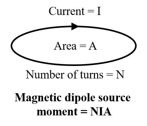
Fig. 178 Moment of an airborne EM loop source.
Moment: The strength of a magnetic dipole source is specified by dipole moment, a quantity defined as the product of the effective area and the current Fig. 178. A high moment can generate greater excitations and thus improves the quality of data in a noisy environment, but the actual area and current of the loop are limited by the power supply and other practical restrictions.
Multi-frequency: EM waves at different frequencies penetrate different depths of the earth because of the skin effect Fig. 179. Depth resolution is gained by using multiple loop sources operating at multiple frequencies.
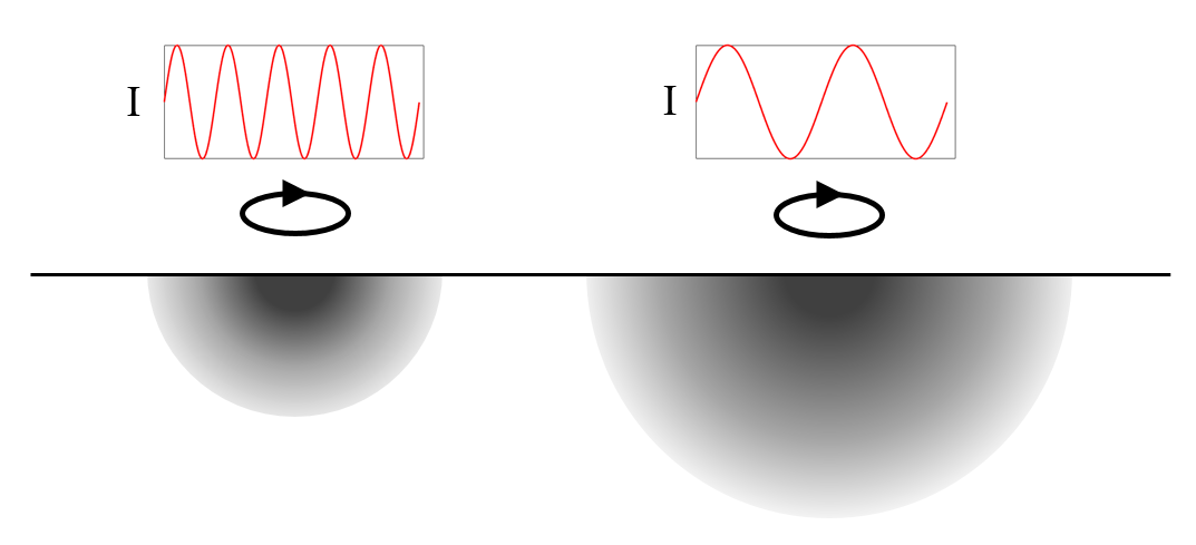
Fig. 179 Depth resolution with multiple frequencies.
Receiver
Loop: A receiver is another loop similar to the transmitter, except it is connected to electronics that measure the electromotive force (EMF, ε) in Volt induced by any external time-varying magnetic fields. Each transmitter loop at a particular frequency has a pairing receiver loop that horizontally offsets the transmitter by a few meters and is designed only receiving signals at that frequency.
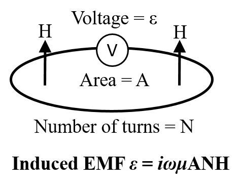
Fig. 180 The EMF measured at the receiver loop is proportional to the magnetic field.
Measurement: The induced EMF is proportional to the rate of change of the magnetic flux through the area enclosed by the loop (\(\varepsilon = - \frac{d \Phi}{~d \mathbf{t}} = ~i \omega \Phi\)). Because the loop is much smaller than the wavelength of the magnetic field in an airborne FDEM survey, the magnetic field at the receiver can be considered uniform. The total magnetic flux is then approximated by the product of magnetic flux intensity and the effective area of the receiver loop. Then the measured EMF can be used to calculate the magnetic field (H) at the receiver (\(\varepsilon = ~i \omega \Phi = ~i \omega B A N = ~i \omega \mu A N H\)), as the frequency, the magnetic permeability and the effective area are known.
Primary removal: The EMF measured at the receiver loop contains the effect of magnetic fields from both the transmitter current and the eddy current in the earth. The primary field (Hp) from the transmitter is several orders of magnitude greater than the secondary field (Hs) from the earth. Since we are only interested in the earth’s response, it is desirable to remove the effect of the primary field from the measured signals. In many FDEM systems, Hs is obtained by using buckling coils that exactly cancels the primary field at the position of the receiver loop Fig. 181. Additional methods may be used to find a zero-primary reference level in the instrument (e.g. phase calibration, gain calibration, internal Q-coil calibration,etc.).
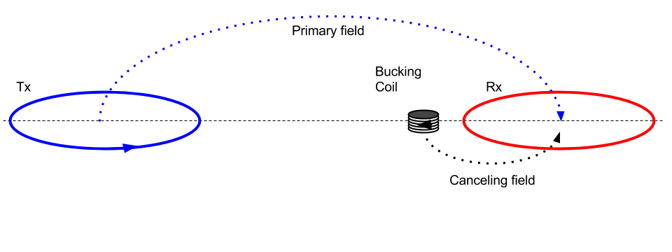
Fig. 181 The primary magnetic field at the receiver is cancelled by a bucking coil.
Configurations
Orientation: There are two commonly-used transmitter-receiver geometries: horizontal coplanar (HCP) and vertical co-axial (VCA). The combination of HCP and VCA provides different ways of coupling with the geological targets oriented in different angles.
Separation: A transmitter-receiver pair is usually two coils that are separated a few meters apart. For low-induction number (separation \(\ll\) skin depth), this separation may be negligible, but for high frequency or very conductive ground, the separation can significantly affect the measured data.
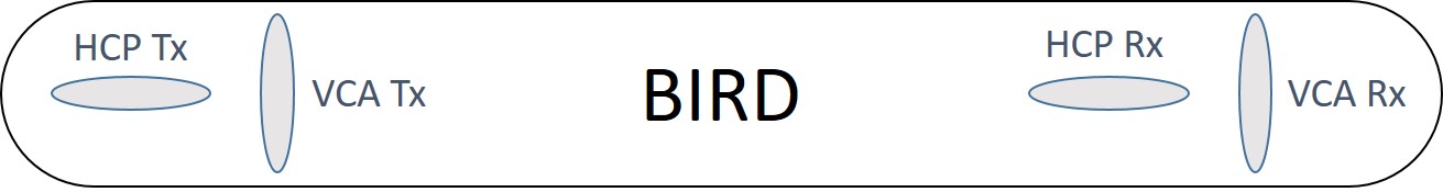
Fig. 182 A diagram of a possible arrangement of HCP and VCA coils in a towed bird.
Field Operation
During production, the bird is towed by a helicopter flying along lines and the EM data are measured during the flight.
Flight
Clearance: A helicopter-towed FDEM bird is typically at least 20 or 30 metres above the surface. Although a higher spatial resolution is desirable by flying the system as close to the ground as possible, a sufficient clearance must be maintained for safety and piloting reasons. In mountainous regions or over tall trees, the system may need to fly higher.
Line spacing: An airborne FDEM survey usually consists of a group of flight lines that are straight and parallel to each other. The spacing between lines is determined by the resolution requirement of the survey and also the geology. Typically an AFDEM system has a line spacing from 50 to 200 meters for applications from geotechnical to resource reconnaissance.
Speed: A slow-flying FDEM system can measure more sounding samples per line-kilometre. However, a higher spatial resolution comes at the cost of spending more time in air. As a trade-off, an AFDEM system typically flies at a speed of about 30 m/s.
Positioning
GPS: Differential Global Positioning System (D-GPS) units are used to collect the location of the helicopter and the bird during the flight. Location data is also collected with a base station so post-survey correction to, for example, clock error and satellite orbit are possible.
Altimeter: There are two types of altimeter that determine the actual flight height. A radar altimeter sends radio waves that reflect from the ground back to the helicopter, and times the travel time to calculate the distance. This type of altimeter is usually located in the helicopter, because it has a longer range. A laser altimeter uses a laser beam instead of radio waves. It is more sensitive in the low range than the radar, so it is often located in the bird. The altitude is measured several times in a second during a flight.
Orientation: The inertia measurement unit (IMU) is used to record the orientation of the bird. It records g-force and angular rate of the bird using accelerometers and gyroscopes.
Post-processing and corrections
The processing and correction implemented by the service providers before data delivery may include:
Base level correction
Lag correction
Moving window median and Hanning filter
Laser altitude correction for dropouts and variation
Magnetic data lag and diurnal correction and IGRF removed
Systems
This section presents commercial airborne FEM systems.
Call for contributors
If you are a service provider, or have experience with a specific AFEM system and would like to contribute, please contact us.