Mechanisms for Conductivity and Chargeability
Electric and Ionic Conduction
Conduction describes the movement of electrical charge from one location to another. There are two important charge carriers of electrical charge, electrons and ions. Let us define the conductivity as follows:
where \(n\) is the number of charge carriers, \(e\) is charge carried by each charge carrier, and \(\mu_e\) is the mobility of the carriers. By this definition, the conductivity of a rock can be determined by its capability to move charges via electrons and ions. This results in two distinct types of conduction: electric conduction and ionic conduction. Both conductions are related to random motion of particles affected by an applied electric field. However, how charge moves in each conduction process is quite different.
Electric Conductivity
The charge carrier for electric conductivity is the electron, which defines conduction within most metals such as iron and copper. The sharing of valence electrons between metallic atoms allows charges to move freely along the directly of an applied electric field.
Ionic conductivity
Conduction within most rocks is primarily electrolytic, taking place in the connected pore spaces, along grain boundaries and in fractures. Conduction within rocks is typically negligible through the mineral grains or silicate framework [War90]. In this case, the charge carrier mostly consists of dissolved ions; which is why we use the term ionic conductivity.
Ionic conductivity results from the ordered movement of ions in an electrolyte under the application of an external electric field. Without an external electric field, the ions move randomly as a result of thermal agitation and collisions with other ions and atoms. Because both cations (+) and anions (-) are present in an electrolyte, the conductivity can be expressed as
where \(n\) is the number of charge carriers, \(e\) is the charge carried, and \(\mu_m\) is the mobility of the carriers. Here superscripts + and - stand for cation and anion, respectively.
Electrode and Membrane Polarization
The chargeability of Earth materials is essentially an electrochemical effect and can be caused by many factors, not all of which are completely understood. If the ground is chargeable, it responds as if the resistivity were a complex quantity - it behaves somewhat like a leaky capacitor. Therefore the chargeability can be measured in a number of ways using time domain or frequency domain techniques. Aspects affecting the chargeability of a sample include:
There are two primary causes of chargeability, “membrane polarization” and “electrode polarization”. In both cases, the re-distribution of charges after an external DC electric field is applied takes some time to occur. Equivalently, it takes the same amount of time to revert back to a balanced charge distribution once the electric field is removed.
Electrode Polarization
Electrode polarization occurs when pore spaces are blocked by metallic particles (Fig. 15 ). Again, charges accumulate when an electric field is applied. The result is two electrical double layers which contribute to measured voltages (Fig. 16 ).
At interfaces between ionic and metallic conductors (for example, an ore grain within the pore space), there is an impedance associated with getting current to flow across the interfaces. These interfaces look like those illustrating in Fig. 15 and have a simplified circuit analogue shown in Fig. 18. Current can flow across these interfaces via 1) charge transfer (or ion diffusion), or 2) via a capacitive effect (no charge transfer).
Ion diffusion is not easy to model with circuit elements. Instead, this process is frequently described using the Warburg impedance and reaction resistance. The magnitude of the Warburg impedance varies approximately as \(\omega^{-1/2}\). Therefore, the impedance due to ion diffusion actually increases as the frequency decreases.
Note that while it is useful to understand simplified models of the relevant electrical behaviors of surface-electrolyte interactions, all rocks are “dirty” in the sense that they are not simply pure “electrodes”. There are other materials and particles affecting ionic behavior within and outside the diffuse layer, and some of the sample’s constituents will affect the behavior of the fixed layer near and on the liquid-solid interfaces. This has resulted in the creation of many empirical models for describing surface-electrolyte interactions.
Membrane Polarization
Membrane polarization occurs when pore space narrows to within several boundary layer thicknesses (which are the thicknesses of ions adsorbed into a surface). Note that the surfaces of mineral grains naturally possess a weak negative charge which attracts cations (Fig. 19).
When an electric field is applied, the charges cannot flow easily through the “pore throat” so they accumulate (Fig. 20). The result is a net electric dipole which contributes towards any other voltages measured across the rock. Like electrode polarization, this process is non-instantaneous.
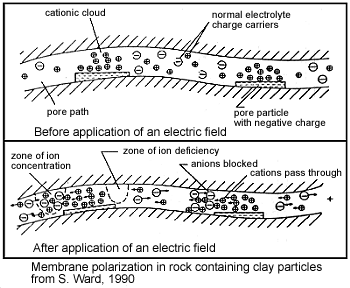
A second form of membrane polarization occurs where clay particles partially block ionic solution pathways (Fig. 22). Upon application of an electric field, positive charge carriers pass easily, while negative carriers accumulate. This is known as an “ion-selective membrane.”
A surplus of both cations and anions occurs at one end of the membrane, while a deficiency occurs at the other end. The reduction of mobility is most obvious at frequencies slower than the diffusion time of ions between adjacent membrane zones; i.e. slower than around 0.1 Hz. Conductivity increases at higher frequencies.

Fig. 22 Membrane polarization.